Premier Manufacturer
ISO13485:2023 Certified
IATF16949: Certified

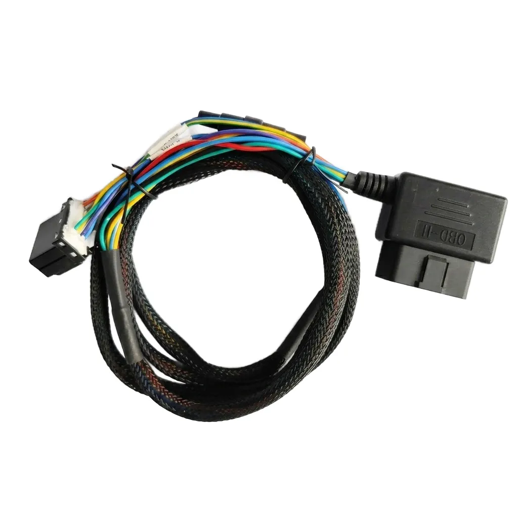
16-Pin OBDII 90° Right-Angle Diagnostic Wire Harness

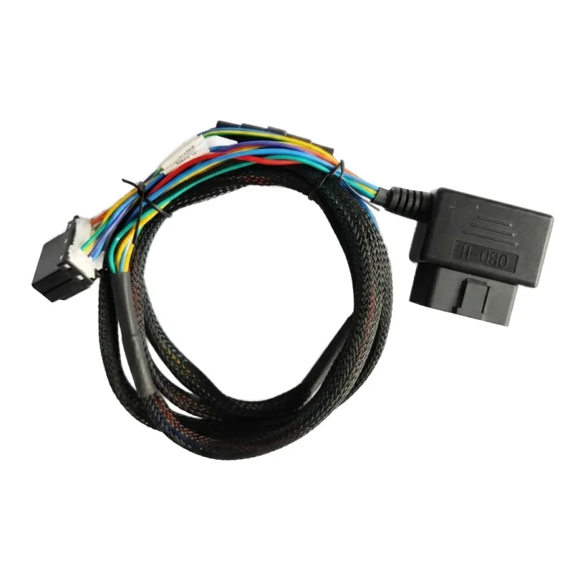
The 16-pin OBDII 90-degree right-angle diagnostic wire harness is designed to connect compatible automotive diagnostic and vehicle tracking equipment to a vehicle’s OBD-II interface. Its angled connector design provides an alternative connection orientation for vehicle installations.

LEX supports OEM wire harness customization based on connector requirements, cable specifications, and application needs.

obdii-16-pin-90-degree-right-angle-wire-harness
Product Overview

Connecting Diagnostic Equipment with Vehicle Systems

The 16-pin OBDII right-angle wire harness is designed to connect compatible automotive diagnostic equipment and vehicle tracking devices to a vehicle’s OBD-II interface. Its 90-degree connector design provides an angled cable exit for different installation and routing requirements.

The cable assembly can be configured according to specific pin assignments, cable lengths, wiring requirements, and opposite-end connections. LEX supports OEM customization based on customer drawings, samples, and application specifications.

Designed for Automotive Diagnostics & Vehicle Connectivity

The 16-pin OBDII interface provides a connection point for compatible diagnostic and telematics equipment. Its 90-degree housing changes the cable exit direction to help accommodate limited clearance around the vehicle’s diagnostic port. Pin assignments and opposite-end connections can be specified according to the connected equipment and project requirements.

16-Pin

OBDII Connector

90°

Right-Angle Design

OBD2

Diagnostic Interface

OEM

Custom Cable Assembly

obdii-16-pin-90-degree-right-angle-wire-harness
Configure the OBDII Cable for Your Equipment Interface

Configure the OBDII Cable for Your Equipment Interface

LEX supports customized 16-pin OBDII diagnostic wire harness assemblies based on equipment interfaces, wiring diagrams, and installation requirements. From 90-degree connector orientation to cable length and opposite-end termination, each configuration is defined according to the approved project specifications.

  • 16-pin OBDII connector interface configuration

  • 90° right-angle connector orientation

  • Custom pin-to-wire mapping based on approved diagrams

  • Flexible cable length and routing

  • Open leads or specified opposite-end connectors

  • Wire specifications and cable protection options

TECHNICAL DATA

16-Pin OBDII Diagnostic Wire Harness Specifications

Technical Parameter Specification Description
Product Type OBDII Diagnostic Wire Harness Automotive diagnostic cable assembly.
Connector Interface OBDII On-board diagnostic connection interface.
Pin Configuration 16-Pin 16-position OBDII connector interface.
Connector Orientation 90° Right Angle Angled connector design for alternative cable routing.
Primary Application Automotive Diagnostics & Tracking Connection to compatible diagnostic and vehicle tracking equipment.
Cable Assembly OBDII Connector Cable Integrated connector and cable assembly.

Final connector wiring, cable dimensions, and electrical specifications should be confirmed against the approved product drawing and application requirements. Contact LEX for detailed technical information and OEM customization.

APPLICATION AREAS

Typical Applications for 16-Pin OBDII Diagnostic Wire Harnesses

The 16-pin OBDII diagnostic wire harness is designed for compatible automotive diagnostic and vehicle connectivity equipment. Its right-angle connector configuration supports different installation and cable routing requirements across automotive diagnostic applications.

automotive-diagnostic-equipment-obdii-16pin-application

Automotive Diagnostic Equipment

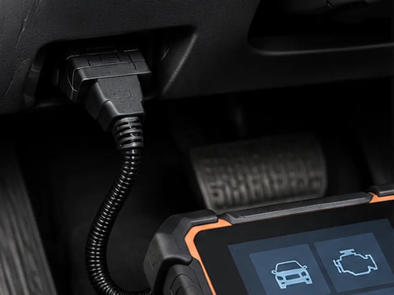
Connects compatible OBD-II diagnostic scanners to vehicle diagnostic interfaces for fault-code reading and vehicle system inspection.

vehicle-tracking-telematics-obdii-16pin-application

Vehicle Tracking & Telematics

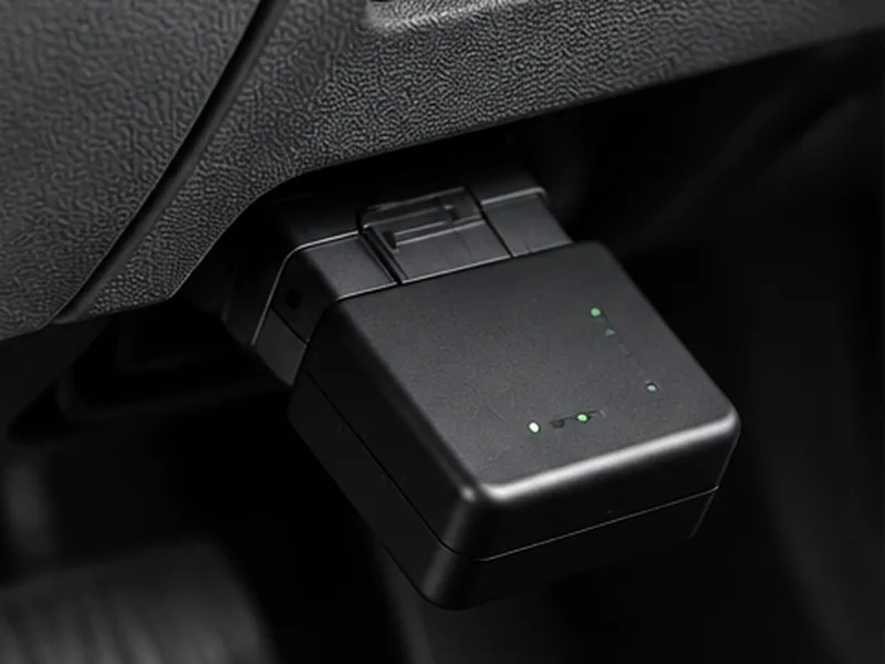
Supports connections between compatible OBD-II interfaces and vehicle tracking or telematics equipment for vehicle data applications.

fleet-diagnostics-data-acquisition-obdii-application

Fleet Diagnostics & Data Acquisition

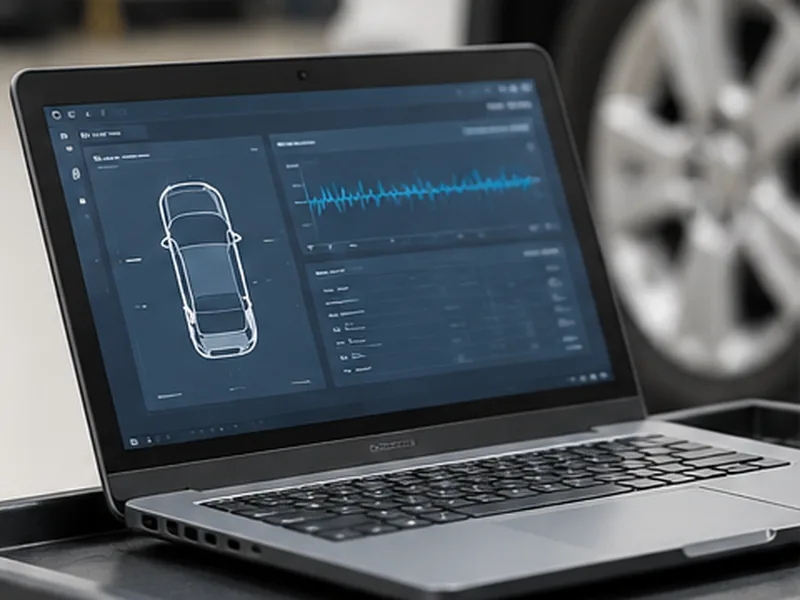
Provides a connection interface for compatible vehicle diagnostic equipment used in fleet inspection, maintenance, and vehicle data collection.

Wire Harness Manufacturing & Assembly

LEX provides comprehensive wire harness manufacturing support, from wire preparation and terminal crimping to harness assembly and electrical testing. Each process follows customer specifications and project requirements.

Engineering & Wiring Review

Review connector specifications, pin assignments, and wiring diagrams.

Wire Cutting & Stripping

Prepare wires according to specified lengths and stripping dimensions.

Terminal Crimping

Ensure secure wire-to-terminal connections through controlled crimping.

Assembly & Verification

Complete harness assembly and verify electrical continuity.

Advanced wire harness production line with organized cable processing, assembly stations, and production equipment.
PRODUCT ENGINEERING

What Defines This 16-Pin OBDII Diagnostic Cable?

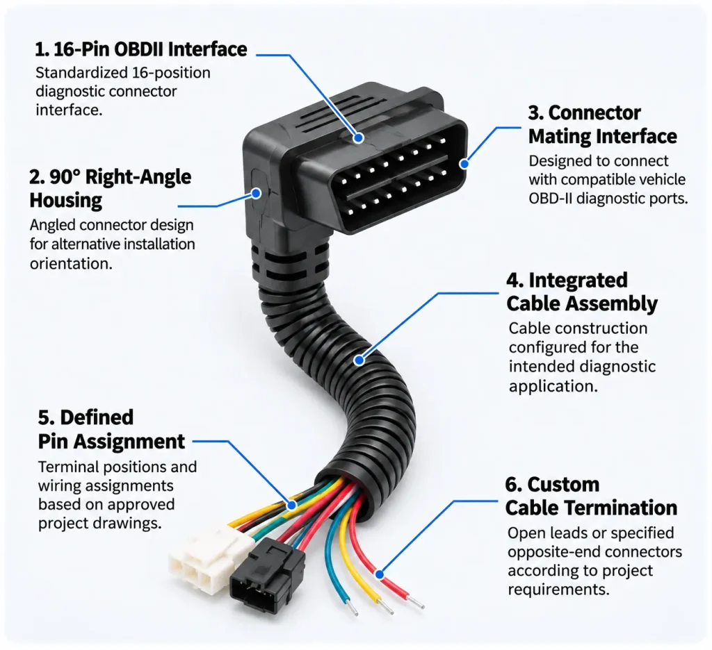
The 16-pin OBDII diagnostic cable combines an angled connector interface with an integrated cable assembly. Its connector orientation, pin configuration, and cable termination are defined according to the requirements of compatible automotive diagnostic and tracking equipment.


16-Pin OBDII Interface

Standardized 16-position diagnostic connector interface.

90° Right-Angle Housing

Angled connector design for alternative installation orientation.

Connector Mating Interface

Designed to connect with compatible vehicle OBD-II diagnostic ports.

Integrated Cable Assembly

Cable construction configured for the intended diagnostic application.

Defined Pin Assignment

Terminal positions and wiring assignments based on approved project drawings.

Custom Cable Termination

Open leads or specified opposite-end connectors according to project requirements.

How to Choose the Right OBDII Diagnostic Wire Harness

Selection Item What to Confirm Why It Matters
OBDII Connector 16-pin connector interface and mating compatibility Ensures proper connection to the vehicle diagnostic port.
Connector Orientation 90-degree right-angle housing and cable exit direction Helps accommodate different dashboard and installation layouts.
Pin Assignment Required terminal positions and circuit mapping Ensures the cable matches the connected diagnostic equipment.
Equipment Compatibility Diagnostic scanner, tracking device, or telematics equipment requirements Prevents interface and wiring mismatches.
Cable Length Required cable length and installation distance Supports suitable routing and equipment placement.
Electrical Requirements Signal, power, grounding, and communication circuit requirements Helps ensure compatibility with the intended application.
Inspection Requirements Continuity, pin-to-pin mapping, and insulation inspection Helps verify wiring accuracy and assembly quality.

Before ordering, confirm the vehicle interface, diagnostic equipment model, required pin assignments, and cable configuration. OBDII connector compatibility alone does not guarantee communication protocol or device compatibility.

DESIGN REVIEW

Common Issues to Resolve Before Wire Harness Production

A pre-production review of drawings, components, wiring, and assembly requirements helps identify potential issues before sampling and mass production.

Incomplete Technical Information

Provide complete drawings, BOM details, connector specifications, wire requirements, and assembly dimensions before production.

Connector & Component Mismatch

Verify connector models, terminal compatibility, mating interfaces, and required accessories against the approved design.

Incorrect Pinout & Wiring

Confirm pin assignments, circuit mapping, polarity, and wire identification to prevent connection errors.

Incorrect Wire Specification

Check wire gauge, conductor type, insulation material, current requirements, and operating conditions.

Cable Length & Routing Issues

Review overall length, branch positions, bend radius, cable routing, and installation clearances.

Unclear Assembly & Inspection Criteria

Define crimping requirements, assembly methods, protection features, and electrical inspection criteria before production.

FREQUENTLY ASKED QUESTIONS

16-Pin OBDII Diagnostic Wire Harness FAQs

For additional information about the 16-pin OBDII diagnostic wire harness, including connector configuration, pin assignments, cable specifications, and OEM customization options, please contact LEX with your project requirements.

01. What is a 16-pin OBDII diagnostic wire harness used for?

A 16-pin OBDII diagnostic wire harness connects compatible automotive diagnostic or tracking equipment to a vehicle’s OBD-II diagnostic interface. It is used in vehicle diagnostics, fault-code reading, telematics, and vehicle data applications.

02. What is the advantage of a 90-degree right-angle OBDII connector?

A 90-degree right-angle OBDII connector provides an angled cable exit direction instead of a straight connection. This design offers an alternative installation orientation and can help accommodate different dashboard layouts and cable routing requirements.

03. Is a 16-pin OBDII cable compatible with all vehicles?

Not necessarily. Although many vehicles use a standardized 16-pin OBD-II diagnostic interface, vehicle compatibility depends on the vehicle’s diagnostic system, supported communication protocols, pin assignments, and connected equipment.

04. Can this OBDII diagnostic cable connect to vehicle tracking devices?

Yes, it is intended for compatible OBD-II vehicle tracking and telematics equipment. Device compatibility, wiring assignments, and communication requirements should be confirmed before ordering.

05. Does a 16-pin OBDII connector mean all 16 pins are wired?

Not necessarily. A 16-position connector describes the connector interface. The actual populated terminals and electrical circuits depend on the specific cable configuration and application requirements.

06. Can LEX customize the length of an OBDII diagnostic wire harness?

LEX supports OEM wire harness customization based on project requirements. Cable length, wiring assignments, connector configurations, and termination details can be reviewed using customer drawings or product samples.

07. What tests are important for an OBDII diagnostic cable assembly?

Important inspection items can include visual inspection, terminal positioning, pin-to-pin continuity, wiring assignment verification, and insulation testing where applicable. The final test requirements depend on the electrical design and customer specifications.

08. What information should I provide when requesting an OBDII cable quotation?

Please provide the required 16-pin connector configuration, 90-degree connector orientation, cable length, wiring diagram, pin assignments, equipment model, estimated order quantity, and any available product drawings or samples.

Get A Quote