26-Pin Molex MicroClasp™ Wire Harness
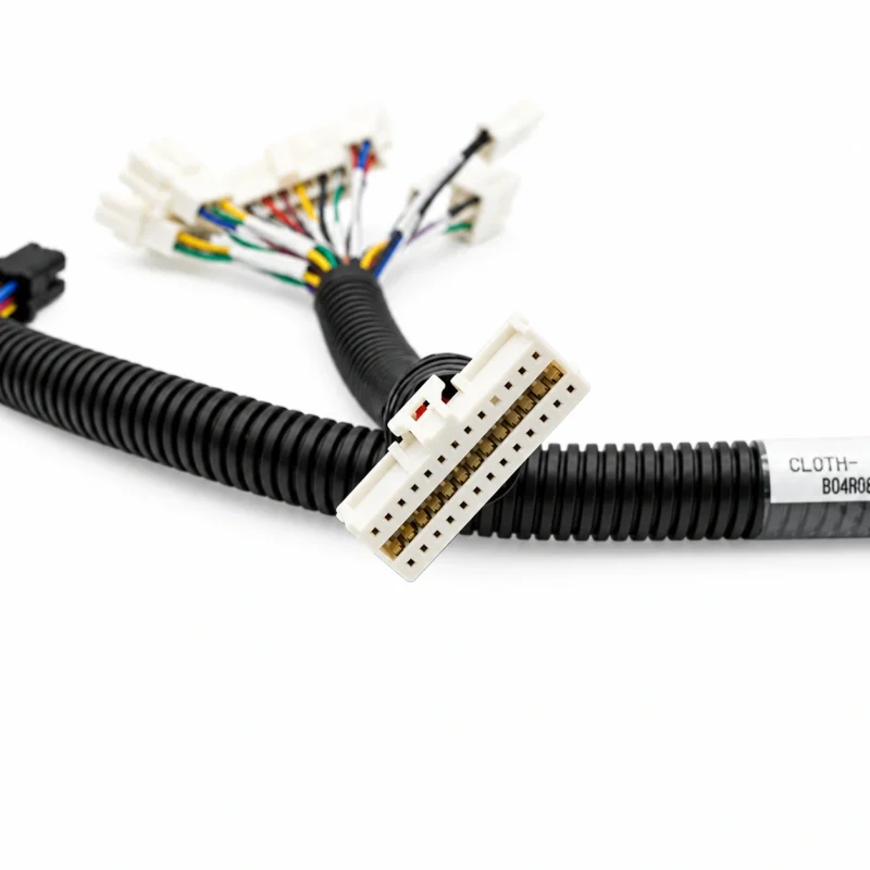
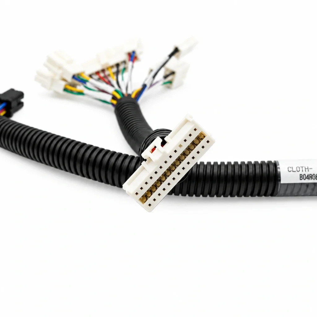
A compact wire-to-board harness assembly built around the Molex 51353-2600, a 2.00mm-pitch, dual-row, 26-circuit MicroClasp receptacle housing. Configure the wire layout, pin mapping and cable routing around your equipment interface.
Molex 51353-2600 Connector-Based Harness Assembly
The Molex 51353-2600 is a 26-circuit, dual-row receptacle housing in the MicroClasp wire-to-board family. LEX uses this connector interface as the basis for a custom cable assembly, with the wiring arrangement defined by the customer’s electrical drawing and mating-board design.
This distinction matters: 51353-2600 identifies the connector housing, while the finished harness also depends on the selected terminals, wires, pin assignment, cable length and opposite-end termination.
Designed for High-Density Signal Connections
The 2.00mm pitch and dual-row layout help consolidate multiple signal circuits into a compact wire-to-board connection. The positive-lock feature helps retain the mated connector when the assembly is installed and handled as intended.
26 Circuits
Dual-row receptacle housing
2.00mm Pitch
Compact wire-to-board interface
Positive Lock
Mechanical retention at the mating interface
Custom Assembly
Pin mapping and wire routing by project
Configure the Harness Around Your Board Interface
LEX can review the connector interface and customer wiring requirements to develop a harness configuration for the target equipment. The final assembly should be defined by a confirmed pinout, mating header and electrical load profile.
Pin-to-wire mapping based on the approved schematic
Custom cable length and routing
Open leads or specified opposite-end connectors
Wire gauge and insulation selection
Wire color and circuit identification
Molex 51353-2600 Technical Specifications
| Technical Parameter | Connector Reference | Harness Configuration |
|---|---|---|
| Connector Part Number | Molex 51353-2600 | Used as the receptacle housing interface |
| Connector Family | MicroClasp 51353 Series | Wire-to-board signal connection |
| Circuit Configuration | 26 circuits, dual row | Pin assignment per approved wiring diagram |
| Pitch | 2.00mm | Matched to the specified PCB header |
| Locking | Positive lock | Mating retention depends on the correct header |
| Mating Headers | 501844 / 55917 vertical; 55959 right-angle | Confirm header orientation and PCB layout |
| Crimp Terminal | Molex 56134 series | Terminal and wire compatibility to be checked |
| Applicable Wire Range | AWG 28–22, per MicroClasp specification | Final gauge selected for load and routing |
| Connector Electrical Ratings | 250V AC/DC maximum; current varies by wire gauge | Assembly rating requires application-level validation |
| Current by Wire Gauge | AWG 22: 3.0A; AWG 24/26: 2.5A; AWG 28: 1.0A | Do not treat as a guaranteed whole-harness rating |
| Housing Material | White nylon | Other cable materials are project-specific |
| Flammability | UL 94 V-0 (connector housing) | Wire and sleeve ratings must be specified separately |
| Connector Operating Temperature | -40°C to +105°C | Selected wire must also meet the required temperature range |
| Product Compliance | Molex product compliance information includes EU RoHS and REACH SVHC status | BOM should confirm material declarations for the complete assembly |
Important: Electrical values above refer to the Molex MicroClasp connector system specification, not an unconditional rating for every finished harness. The usable rating of a complete assembly depends on wire construction, terminal selection, number of simultaneously loaded circuits, ambient temperature and installation conditions.
Typical Applications for 26-Pin MicroClasp Harnesses
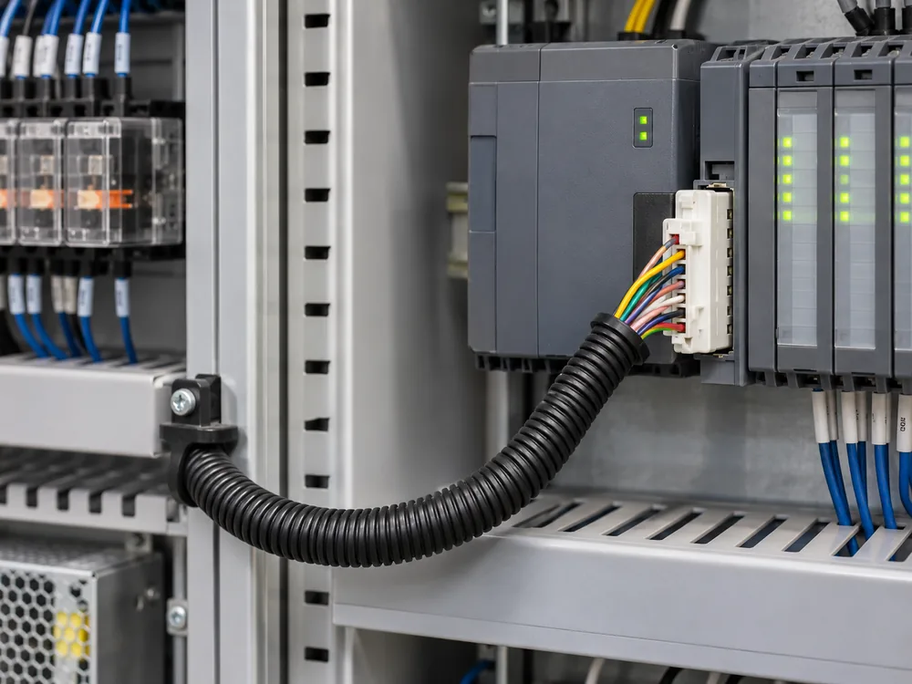
A compact multi-circuit interface can be considered for equipment that needs organized signal connections between a PCB, control module or internal wiring assembly.

Industrial Control Systems
Signal connections between control boards, I/O modules and internal equipment wiring.
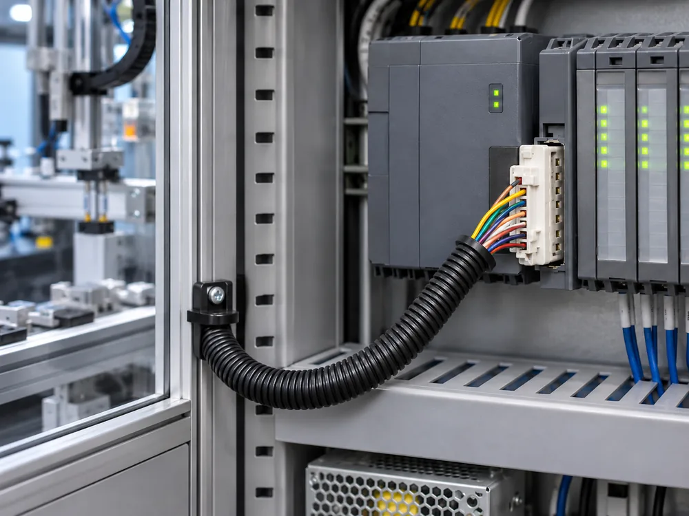
Automation Equipment
Compact harness routing for machine controllers, sensors and electronic subassemblies.

Robotics & Motion Control
Multi-circuit signal wiring inside control units and compact robotic subsystems.
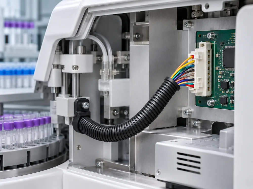
Medical & Laboratory Equipment
Internal signal interconnections for diagnostic and laboratory equipment, subject to device-level validation.
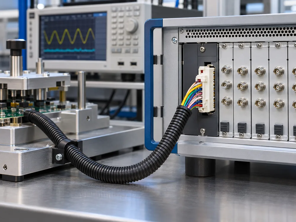
Test & Measurement Devices
Organized circuit connections in instruments, test fixtures and electronic measurement systems.
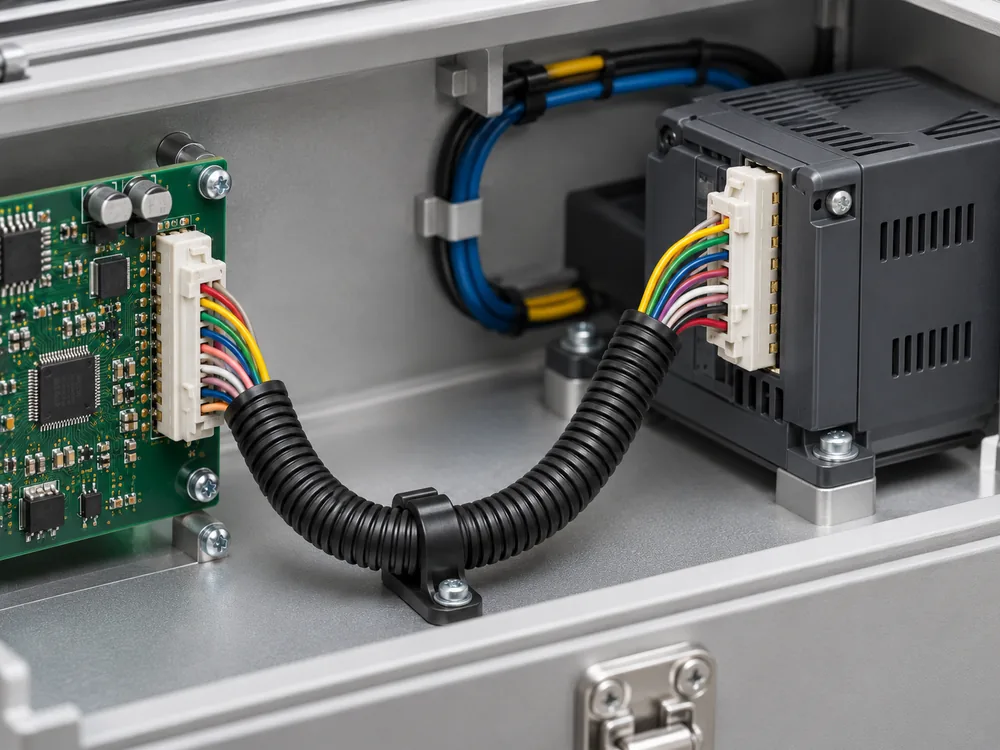
Compact Electronic Assemblies
Wire-to-board connections where circuit density and a defined mating interface are important.

Wire Harness Manufacturing & Assembly
LEX provides comprehensive wire harness manufacturing support, from wire preparation and terminal crimping to harness assembly and electrical testing. Each process follows customer specifications and project requirements.
Engineering & Wiring Review
Review connector specifications, pin assignments, and wiring diagrams.
Wire Cutting & Stripping
Prepare wires according to specified lengths and stripping dimensions.
Terminal Crimping
Ensure secure wire-to-terminal connections through controlled crimping.
Assembly & Verification
Complete harness assembly and verify electrical continuity.
What Defines This 26-Circuit Harness?
The connector interface establishes the mating geometry. The finished cable assembly is then configured around the electrical and mechanical requirements of the equipment.

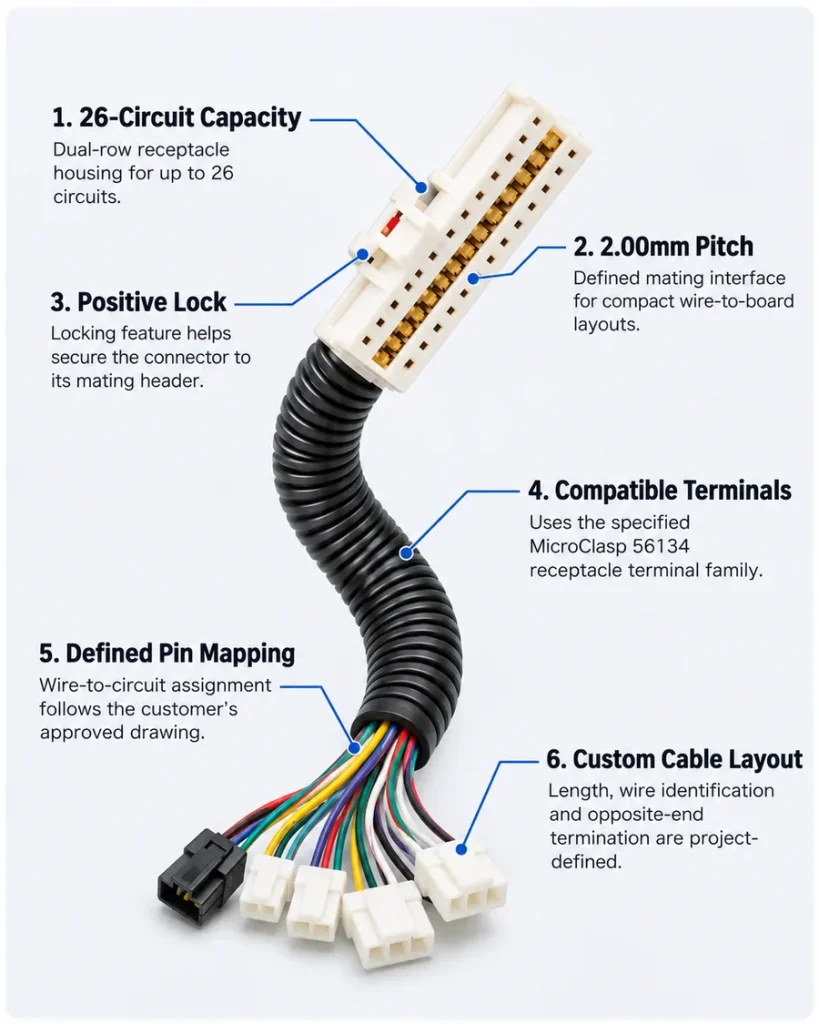
26-Circuit Capacity
Dual-row receptacle housing for up to 26 circuits.
2.00mm Pitch
Defined mating interface for compact wire-to-board layouts.
Positive Lock
Locking feature helps secure the connector to its mating header.
Compatible Terminals
Uses the specified MicroClasp 56134 receptacle terminal family.

Defined Pin Mapping
Wire-to-circuit assignment follows the customer's approved drawing.

Custom Cable Layout
Length, wire identification and opposite-end termination are project-defined.
MicroClasp Harness Selection Guide
| Selection Item | What to Confirm | Why It Matters |
|---|---|---|
| Mating Header | Vertical or right-angle header; exact part number and PCB orientation | Prevents incompatible mating geometry and installation conflicts. |
| Pin Assignment | Complete pin-to-wire list, unused circuits and signal grouping | Reduces cross-wiring and incorrect circuit mapping. |
| Wire Gauge | Current per circuit, wire construction, insulation OD and temperature | Must remain within the terminal and connector application limits. |
| Cable Length | Overall length, branch lengths, tolerance and routing path | Controls fit, service loops and mechanical stress after installation. |
| Opposite-End Connection | Open leads, another connector, PCB termination or customer-defined interface | Defines the finished harness architecture. |
| Protection | Sleeving, conduit, strain relief, abrasion or moisture exposure | Protection must match the actual installation environment. |
| Inspection Plan | Continuity, pin mapping, visual checks and any project-specific tests | Sets clear acceptance criteria before sample approval and production. |
Common Issues to Resolve Before Wire Harness Production
A pre-production review of drawings, components, wiring, and assembly requirements helps identify potential issues before sampling and mass production.
Incomplete Technical Information
Provide complete drawings, BOM details, connector specifications, wire requirements, and assembly dimensions before production.
Connector & Component Mismatch
Verify connector models, terminal compatibility, mating interfaces, and required accessories against the approved design.
Incorrect Pinout & Wiring
Confirm pin assignments, circuit mapping, polarity, and wire identification to prevent connection errors.
Incorrect Wire Specification
Check wire gauge, conductor type, insulation material, current requirements, and operating conditions.
Cable Length & Routing Issues
Review overall length, branch positions, bend radius, cable routing, and installation clearances.
Unclear Assembly & Inspection Criteria
Define crimping requirements, assembly methods, protection features, and electrical inspection criteria before production.
26-Pin Molex MicroClasp Wire Harness FAQs
Answers to common engineering and sourcing questions about the 51353-2600 connector-based cable assembly.
1. Is Molex 51353-2600 a complete wire harness?
No. Molex 51353-2600 is a 26-circuit, dual-row MicroClasp receptacle housing. A finished wire harness also requires compatible crimp terminals, wires, a defined pin assignment, and the specified opposite-end termination. LEX can build the cable assembly around the connector interface according to the project drawing.
2. What is the pitch and circuit arrangement of the 51353-2600?
The connector is a 2.00mm-pitch MicroClasp receptacle housing with a dual-row arrangement and a maximum of 26 circuits.
3. Which mating headers are used with the 51353-2600 housing?
Molex lists dual-row vertical headers 501844 and 55917, and the dual-row right-angle header 55959 as mating parts. The correct header must be confirmed against the PCB layout and required mating orientation.
4. Which crimp terminals are compatible with this MicroClasp housing?
The MicroClasp application documentation identifies the 56134 receptacle terminal series for the harness side. The exact terminal variant and wire compatibility should be checked against the current Molex specification.
5. Can LEX customize the wire length and pin assignment?
Harness length, pin-to-wire mapping, wire colors, branch layout, and opposite-end termination can be defined for a custom project. Please provide the wiring diagram, mating connector information, and target cable requirements for review.
6. Is the standard Molex 51353-2600 connector waterproof?
The standard 51353-2600 receptacle housing is not identified as a sealed IP-rated connector in the published product specifications. If the application requires dust or moisture protection, the complete assembly needs an appropriate enclosure or protection design and project-specific validation.
7. What information should I send for a quotation?
Send the mating header part number, pinout or wiring diagram, wire gauge, cable length, opposite-end connection, quantity, operating environment and required inspection or test criteria. A sample or existing harness can also help clarify the assembly requirements.