
Premier Manufacturer
ISO13485:2023 Certified
IATF16949: Certified

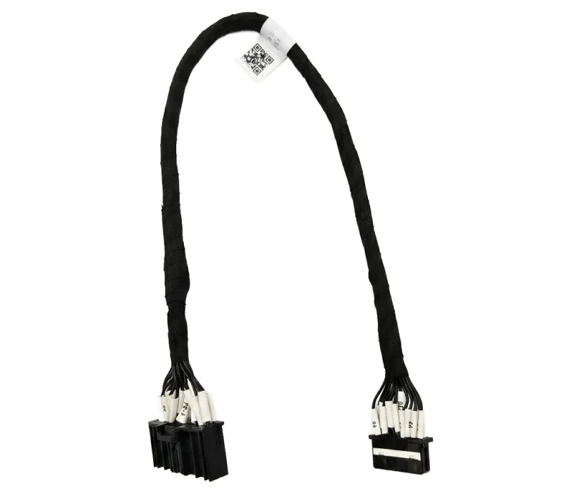
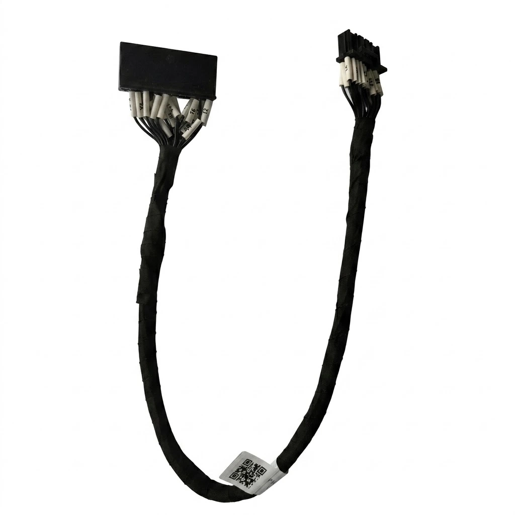
BMS Signal Wire Harness for Battery Energy Storage Systems

LEX provides BMS signal wire harness assemblies for battery energy storage systems, connecting specified battery monitoring interfaces, control modules and electrical components. Each assembly can be configured around connector types, pin assignments, cable lengths and wiring layouts to meet the requirements of your BESS application.

bess-energy-storage-bms-wire-harness
Product Overview

BMS Signal Connections for Battery Energy Storage Systems

A BMS signal wire harness connects designated electrical interfaces within a battery management system, providing organized wiring between battery monitoring components, control modules and related equipment.

For battery energy storage systems, the harness configuration depends on the system architecture, connector interfaces, circuit assignments and installation layout. The wiring arrangement must follow the approved electrical drawings to ensure that each connection matches its intended function.

LEX manufactures BMS wiring harness assemblies according to customer specifications, with configurable connector combinations, wire lengths, conductor identification and protective sleeving. From individual battery modules to larger BESS assemblies, each harness is prepared around the actual connection requirements of the equipment.

Configured Around Your BMS Wiring Architecture

Each BMS wire harness is configured around the connection points and electrical requirements of your battery management system. Connector compatibility, circuit assignments, cable branches and wire identification are reviewed against your approved wiring diagrams to ensure the finished assembly matches the intended system layout.

BMS Interfaces

Battery monitoring and control connections

Connector Options

Customer-specified mating interfaces

Pin Mapping

Defined circuit-to-circuit assignments

OEM Assembly

Project-specific cable configuration

bess-energy-storage-bms-wire-harness-1
Custom Design & Engineering

What We Review Before BMS Harness Production

Before production, LEX reviews the electrical drawings, connector interfaces and installation requirements of each BMS wire harness project. This helps identify potential compatibility issues, wiring errors and assembly requirements before sample development and production.

☑ BMS Connector Part Numbers & Compatibility

☑ Approved Pin-to-Pin Wiring Diagram

☑ Signal Circuit & Wire Specifications

☑ Cable Length & Branch Configuration

☑ Protective Sleeving & Wire Identification

☑ Electrical Testing & Inspection Requirements
TECHNICAL DATA

How to Specify a BMS Signal Wire Harness

Selecting the right BMS wiring harness starts with the electrical interface and system layout. Connector specifications, pin assignments, wire requirements and cable routing should all be confirmed before production to ensure the assembly matches the intended battery management system.

Selection Item What to Confirm Why It Matters
BMS Interface BMS controller model, connection points and interface specifications. Ensures the harness matches the intended battery management equipment.
Connector Type Connector manufacturer, part number, pin count and mating interface. Prevents connector mismatch during system integration.
Pin Assignment Complete pin-to-pin wiring diagram and circuit identification. Ensures each conductor connects to its designated circuit.
Signal Requirements Signal types, electrical characteristics and communication requirements. Defines the appropriate wire and connector configuration.
Wire Specification Wire gauge, conductor material, insulation and shielding requirements. Supports suitable electrical and mechanical performance.
Cable Length Overall length, individual branch lengths and routing distance. Helps accommodate the actual battery rack and equipment layout.
Branch Configuration Branch quantity, connection positions and branch orientation. Ensures the harness follows the intended system wiring architecture.
Wire Identification Wire colors, labels, circuit numbering and marking methods. Simplifies installation, troubleshooting and maintenance.
Protection Requirements Sleeving, heat-shrink, insulation and environmental conditions. Helps match the harness construction to its installation environment.
Inspection Requirements Continuity, pin mapping, insulation and project-specific acceptance criteria. Defines the inspection requirements before delivery.

Providing the BMS wiring diagram, connector part numbers and installation requirements helps our engineering team evaluate the appropriate harness configuration before quotation and production.

APPLICATION AREAS

BMS Wire Harness Applications Across Energy Storage Systems

BMS signal wire harnesses support electrical connections between battery monitoring components, management controllers and related equipment across different energy storage systems. Each harness configuration is designed around the system architecture, connector interfaces and wiring requirements.

utility-scale-battery-energy-storage-system

Utility-Scale Battery Energy Storage Systems

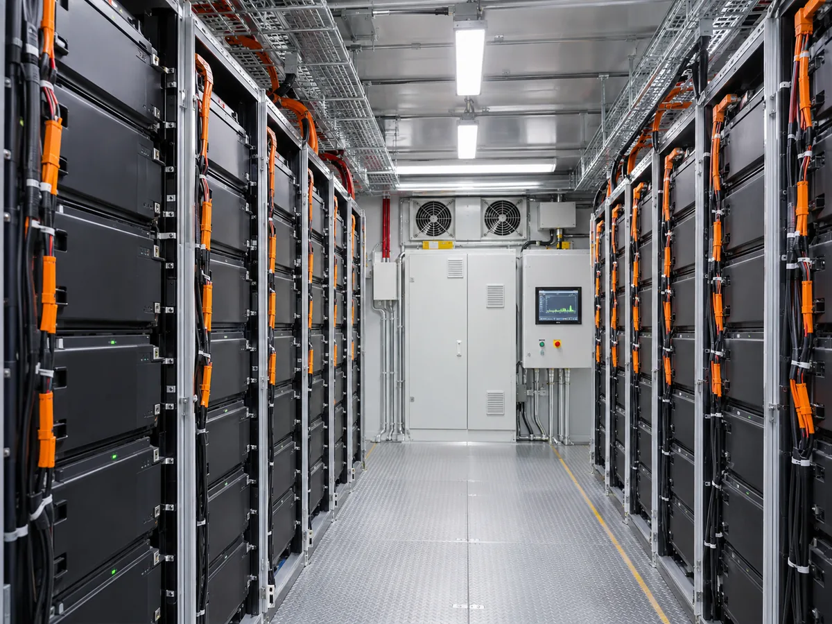
Used in large-scale battery energy storage installations to connect designated monitoring interfaces and control components across battery racks, containers and system enclosures.
commercial-industrial-energy-storage-system

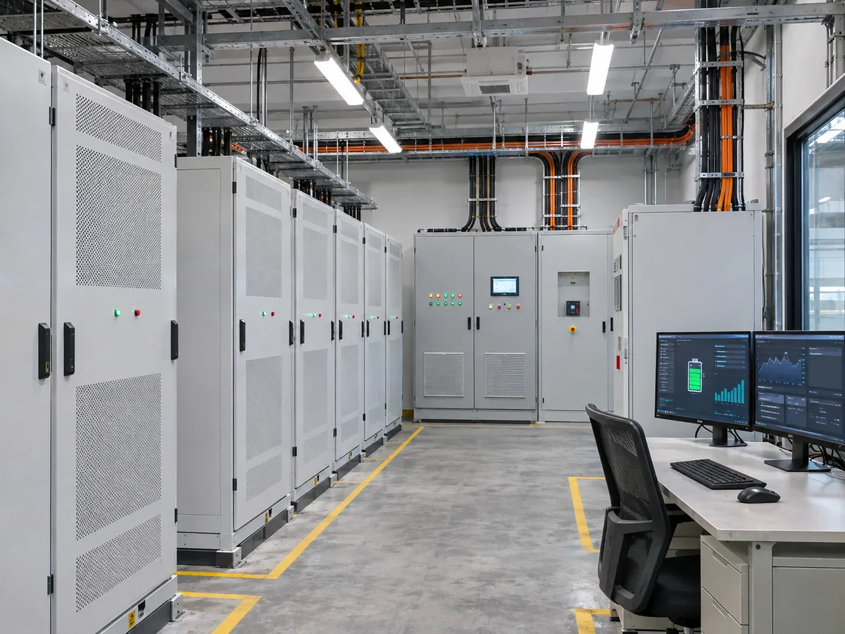
Commercial & Industrial Energy Storage

Supports signal connections between battery modules, BMS controllers and monitoring equipment in commercial and industrial energy storage cabinets.
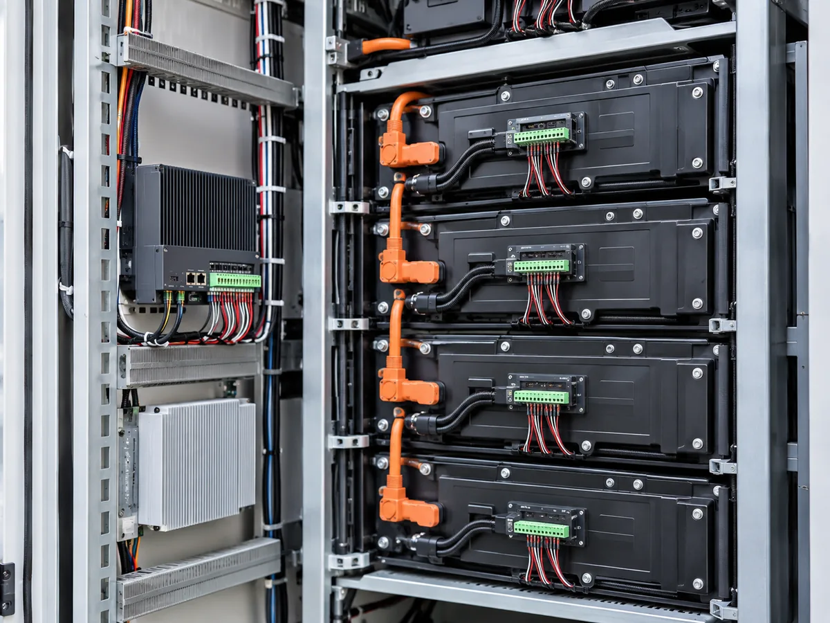
battery-rack-module-monitoring-system

Battery Rack & Module Monitoring

Provides organized wiring connections between battery modules and rack-level battery management components according to the specified monitoring architecture.
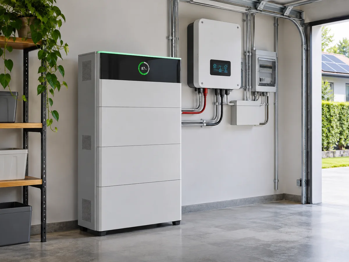
residential-battery-energy-storage-system

Residential Battery Energy Storage Systems

Designed for compatible residential battery storage equipment requiring configured signal connections between battery modules, monitoring interfaces and management controllers.

Wire Harness Manufacturing & Assembly

LEX provides comprehensive wire harness manufacturing support, from wire preparation and terminal crimping to harness assembly and electrical testing. Each process follows customer specifications and project requirements.

Engineering & Wiring Review

Review connector specifications, pin assignments, and wiring diagrams.

Wire Cutting & Stripping

Prepare wires according to specified lengths and stripping dimensions.

Terminal Crimping

Ensure secure wire-to-terminal connections through controlled crimping.

Assembly & Verification

Complete harness assembly and verify electrical continuity.

Advanced wire harness production line with organized cable processing, assembly stations, and production equipment.
Design Review

What Defines a BMS Signal Wire Harness?

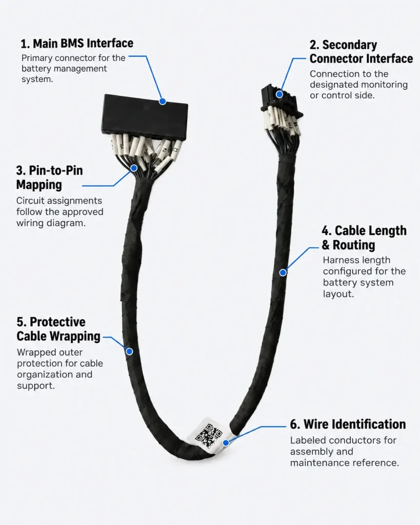
A BMS signal wire harness is defined by more than its cable and connectors. Its configuration depends on the electrical interfaces, circuit assignments, routing requirements and protection methods specified for the battery management system.

BMS Connector Interface

Connector type and mating geometry specified for the battery management system.

Secondary Connector Interface

Compatible connection to the designated monitoring or control equipment.

Pin-to-Pin Mapping

Circuit assignments defined by the approved electrical drawing.

Cable Length & Routing

Cable dimensions configured for the actual battery system layout.

Protective Cable Sleeving

Sleeving and heat-shrink options selected according to assembly requirements.

Wire Identification

Wire colors, labels and circuit numbering specified for installation and maintenance.

How to Specify a BMS Signal Wire Harness

Selecting the right BMS wiring harness starts with the electrical interface and system layout. Connector specifications, pin assignments, wire requirements and cable routing should all be confirmed before production to ensure the assembly matches the intended battery management system.

Selection Item What to Confirm Why It Matters
BMS Interface BMS controller model, connection points and interface specifications. Ensures the harness matches the intended battery management equipment.
Connector Type Connector manufacturer, part number, pin count and mating interface. Prevents connector mismatch during system integration.
Pin Assignment Complete pin-to-pin wiring diagram and circuit identification. Ensures each conductor connects to its designated circuit.
Signal Requirements Signal types, electrical characteristics and communication requirements. Defines the appropriate wire and connector configuration.
Wire Specification Wire gauge, conductor material, insulation and shielding requirements. Supports suitable electrical and mechanical performance.
Cable Length Overall length, individual branch lengths and routing distance. Helps accommodate the actual battery rack and equipment layout.
Branch Configuration Branch quantity, connection positions and branch orientation. Ensures the harness follows the intended system wiring architecture.
Wire Identification Wire colors, labels, circuit numbering and marking methods. Simplifies installation, troubleshooting and maintenance.
Protection Requirements Sleeving, heat-shrink, insulation and environmental conditions. Helps match the harness construction to its installation environment.
Inspection Requirements Continuity, pin mapping, insulation and project-specific acceptance criteria. Defines the inspection requirements before delivery.

Providing the BMS wiring diagram, connector part numbers and installation requirements helps our engineering team evaluate the appropriate harness configuration before quotation and production.

DESIGN REVIEW

Common Issues to Resolve Before Wire Harness Production

A pre-production review of drawings, components, wiring, and assembly requirements helps identify potential issues before sampling and mass production.

Incomplete Technical Information

Provide complete drawings, BOM details, connector specifications, wire requirements, and assembly dimensions before production.

Connector & Component Mismatch

Verify connector models, terminal compatibility, mating interfaces, and required accessories against the approved design.

Incorrect Pinout & Wiring

Confirm pin assignments, circuit mapping, polarity, and wire identification to prevent connection errors.

Incorrect Wire Specification

Check wire gauge, conductor type, insulation material, current requirements, and operating conditions.

Cable Length & Routing Issues

Review overall length, branch positions, bend radius, cable routing, and installation clearances.

Unclear Assembly & Inspection Criteria

Define crimping requirements, assembly methods, protection features, and electrical inspection criteria before production.

FREQUENTLY ASKED QUESTIONS

BMS Signal Wire Harness Frequently Asked Questions

Every BMS installation has different connection and wiring requirements. If you have a battery management system drawing or an existing harness sample, share it with our team for an engineering review and quotation.

01. What is a BMS signal wire harness used for?

A BMS signal wire harness connects designated monitoring, communication and control interfaces within a battery management system. It provides organized electrical connections between specified battery components and BMS equipment.

02. What is the difference between a BMS signal harness and a battery power cable?

A BMS signal harness carries monitoring or control signals, while battery power cables are designed for power transmission during charging and discharging. Their conductor sizes, insulation requirements and connection designs differ.

03. Can BMS wire harnesses be customized for different battery management systems?

Yes. Harness configurations can be developed according to the BMS model, connector interfaces, pin assignments, cable dimensions and customer-provided wiring diagrams.

04. Can you manufacture multi-branch BMS wiring harnesses?

Yes. Multi-branch configurations can be manufactured according to approved drawings, including specified branch lengths, connector positions and circuit assignments.

05. What connector types can be used in a BMS harness?

Connector selection depends on the BMS hardware and mating interfaces. Molex, JST, TE and other compatible connector options can be evaluated according to the required part numbers and specifications.

06. How are pin assignments verified during production?

Pin assignments can be checked against the approved wiring diagram through pin-to-pin continuity testing and wiring verification according to the project inspection requirements.

07. What information is needed for a custom BMS harness quotation?

Please provide connector part numbers, pin assignments, wire specifications, cable lengths, branch layouts, estimated quantities and available engineering drawings.

08. Can BMS signal harnesses be manufactured from customer drawings or samples?

Yes. LEX can review customer drawings, wiring diagrams or physical samples to evaluate the required connector configuration, cable construction and assembly details.

Get A Quote